


Views: 0 Author: Site Editor Publish Time: 2026-09-08 Origin: Site


A drilling rig relies on continuous circulation to survive. We often think of the rig as drill pipes and top drives. However, the mechanical heart driving the entire operation is the pump. If it fails, mud stops flowing immediately. Cuttings settle, the drill string gets stuck, and downtime costs skyrocket. Understanding how this vital equipment operates goes beyond simple mechanics. You need a solid grasp of component-level operations to make smart procurement decisions. It helps you evaluate performance specs. It allows you to estimate maintenance intervals accurately. It ensures complete rig compatibility for demanding jobs. This guide strips away confusing sales jargon entirely. We will examine the physical mechanisms and structural differences of these fluid drivers. You will learn the exact criteria needed to evaluate pump viability for heavy-duty drilling operations. Let us dive into the core engineering keeping drilling fluids moving under extreme conditions.
The primary function of a drilling mud pump is to circulate drilling fluid under high pressure down the drill string and back up the annulus, carrying cuttings to the surface.
Operations are split between two main assemblies: the power end (converting rotational energy) and the fluid end (driving the fluid).
Triplex mud pumps have largely replaced duplex models due to lower weight, reduced fluid pulsation, and higher mechanical efficiency.
Evaluating a pump requires balancing theoretical flow rates (GPM) and pressure (PSI) with the physical realities of footprint, consumable wear rates, and maintenance accessibility.
The entire system relies on two main sections. We call these the power end and the fluid end. The power end handles energy conversion. A diesel engine or electric motor provides raw mechanical power. Heavy-duty belts, roller chains, or gear systems transfer this energy. They connect directly to the main crankshaft. This rotational motion must change into linear motion to be useful. A crosshead mechanism achieves this transformation. It slides back and forth inside machined guides. This sliding action pushes the pony rods outward and pulls them back continuously.
The fluid end takes over next. It manages fluid displacement. A Drilling mud pump relies on a continuous mechanical cycle. We can break this down into clear suction and discharge strokes. Here is how the process works in practice:
The piston moves backward, creating a strong internal vacuum inside the cylinder.
The vacuum pulls the suction valve open against its tension spring.
Drilling fluid rushes into the chamber from the external holding tanks.
The piston reverses direction, driving forward aggressively.
The forward motion slams the suction valve shut instantly.
Rising internal pressure forces the discharge valve open.
The system pushes fluid out into the discharge manifold under extreme pressure.
Energy transfer efficiency matters greatly here. It directly dictates fuel consumption. It also determines your required motor sizing. Poor conversion means wasted energy and higher operational friction. You must ensure seamless power delivery to maintain consistent flow rates.
The internal environment is brutally harsh. Fluid displacement relies heavily on a Piston mud pump mechanism. You will find three critical components interacting here. They are the piston, the liner, and the valves. These parts interact constantly under immense mechanical stress. They handle massive pressure spikes during every single stroke.
Drilling mud is highly abrasive. It carries sharp rock fragments and heavy barite additives. This mixture acts like liquid sandpaper. Physics dictates a rapid and unavoidable wear cycle. Constant friction exists between the moving piston and the stationary liner. This friction generates immense heat and physical degradation. It strips away protective elastomer seals over time. Even premium polyurethane pistons degrade under these brutal conditions.
Many buyers fall for the myth of maintenance-free equipment. You must ignore this claim completely. Liners and pistons will inevitably fail during active operations. You cannot prevent this mechanical reality. Instead, focus on replacement speed. Your crew must swap these parts quickly. Easy access to the fluid end is crucial. Fast component replacement directly impacts operational profitability. If your crew struggles for hours to change a single liner, rig downtime multiplies rapidly.
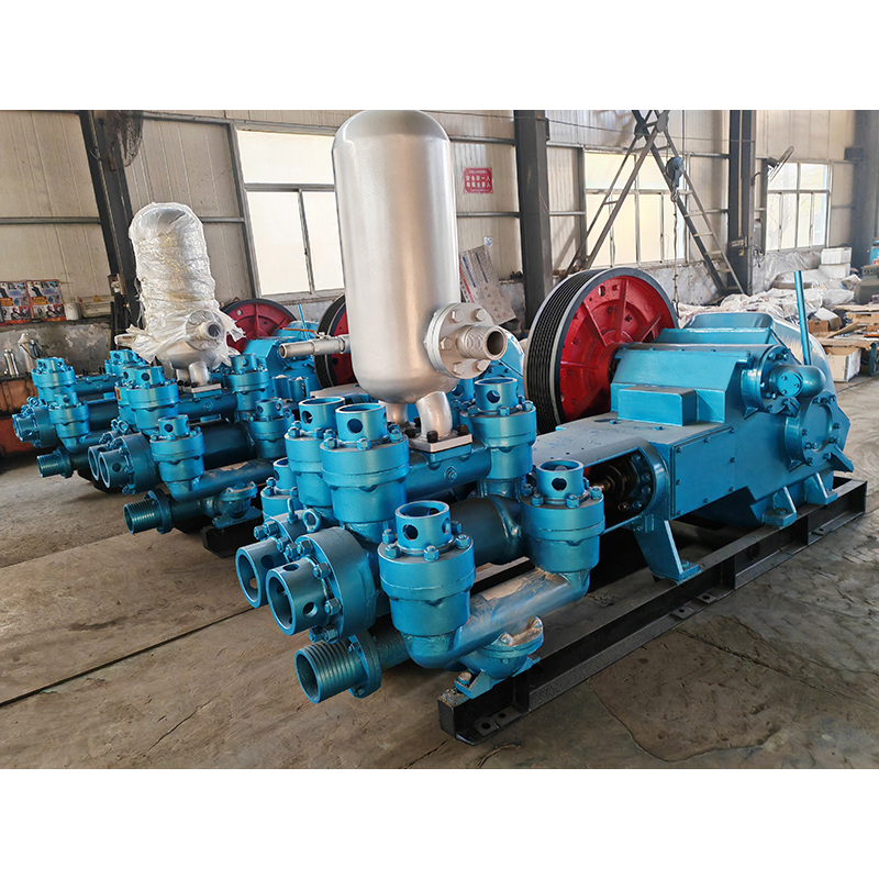
Engineers historically relied on duplex pumps. These are double-acting systems. They pump fluid on both the forward and backward strokes. You get continuous fluid movement from fewer cylinders. However, they carry severe operational drawbacks. Duplex designs demand a massive physical footprint. They are incredibly heavy. They also generate high pressure pulsations. Maintenance is notoriously difficult. The dual-acting seals require complex replacement procedures. Field crews often hate servicing them.
Today, the industry strongly prefers the Triplex mud pump. This single-acting design uses three pistons. They only pump fluid on the forward stroke. The cylinders are phased exactly 120 degrees apart. This mathematical setup provides a massive business advantage. You get a much lighter unit overall. It produces up to 30% less pulsation compared to older models. This smoother flow protects sensitive downstream pipework.
You can push higher operational pressure limits safely. Most importantly, it simplifies fluid end maintenance significantly. Crews only service one side of the piston. Modern drilling requires higher pressures and tighter tolerances. Triplex designs deliver exactly this required performance. Legacy duplex systems still have a place occasionally. You might justify them for budget-constrained shallow water well drilling. Otherwise, modern rigs demand three-cylinder single-acting performance.
Architecture Comparison: Duplex vs. Triplex Designs
Feature Category | Duplex Designs | Triplex Designs |
|---|---|---|
Action Type | Double-acting (pumps both ways) | Single-acting (forward only) |
Cylinder Count | Two | Three |
Physical Weight | Extremely heavy | Significantly lighter |
Pulsation Level | High hydraulic shock | Up to 30% lower pulsation |
Maintenance Speed | Complex and slow | Simplified and fast |
Selecting the right equipment requires balancing multiple engineering variables. You cannot look at a single metric in isolation.
Your pump output must match your specific well profile perfectly. You must consider the hole diameter and total depth. The specific rheology of your fluid also matters greatly. Deep wells require higher PSI to overcome extreme annular friction. Large diameter holes need higher GPM to clear cuttings effectively. You must calculate these requirements before purchasing any unit.
Engineers face a constant tradeoff here. Longer strokes at lower RPMs usually perform much better. They provide excellent volumetric efficiency. They also reduce wear on fluid end consumables. The piston changes direction less frequently. Short strokes at high RPMs generate excessive heat. They destroy piston rubbers much faster. We recommend prioritizing longer stroke lengths for sustained operations.
Rig mobility dictates your equipment size limits. You must evaluate the mud pump skid dimensions closely. Compare these dimensions against onshore highway transport limits. Consider maximum crane lifting capacities for offshore platforms. A heavy unit might delay rig mobilization schedules entirely. Lighter skids offer better logistical flexibility.
Continuous load stresses metal to its breaking point. You need extreme material integrity to survive these forces. Look specifically for forged steel fluid ends. Cast metal cannot handle modern pressure spikes safely. Power end components require high-alloy construction. These premium materials prevent catastrophic cracking during continuous 24/7 operation.
Verify the maximum required GPM for optimal hole cleaning.
Calculate the peak PSI needed for reaching total depth.
Measure the allowable skid footprint for easy rig transport.
Confirm the fluid end uses premium forged steel blocks.
Even the best equipment fails under poor operational management. You must understand hydraulic risks to protect your mechanical assets.
Reciprocating pumps inherently create pressure spikes. We use nitrogen-charged dampeners to smooth out these hydraulic shocks. What happens when this dampener fails? The results are immediately severe. You will see rapid fatigue on drill lines. Surface pipework will shake violently. This vibration causes highly inaccurate MWD (Measurement While Drilling) readings. It ruins LWD (Logging While Drilling) telemetry completely. You must ensure proper nitrogen pre-charge pressure daily. A flat dampener transfers destructive energy directly into the rig structure.
Fluid must flow seamlessly into the suction manifold. Poor setup interrupts this flow drastically. Improper suction line sizing is a very common mistake. A pipe too small restricts fluid intake. Poor centrifugal charge pump integration also creates massive problems. These errors lead directly to cavitation. Cavitation occurs when vapor bubbles form and collapse violently inside the chamber. These micro-explosions literally chip away at internal metals. They destroy forged fluid ends prematurely. Always maintain a positive feed pressure. A well-designed charge system eliminates this costly threat entirely.
A pump relies on simple working principles fundamentally. However, engineering a reliable unit requires high-precision manufacturing. The power end and fluid end must work in perfect harmony. You need seamless energy transfer and robust fluid displacement.
We advise buyers to look beyond raw horsepower vanity metrics. Vanity numbers look great on sales brochures. They do not pump fluid efficiently in the field. Instead, prioritize fluid end accessibility. Focus on rapid component availability. Ensure exact GPM and PSI matching for your specific well profiles. Make maintenance ease a top priority.
Take proactive next steps before signing procurement orders. We encourage operators to consult directly with pump engineers. Request historical MTBF (Mean Time Between Failures) data for specific models. Review detailed spec sheets carefully. Understand the mechanical tradeoffs completely. Smart evaluation guarantees continuous circulation. This diligence ultimately protects your entire drilling investment.
A: A triplex design uses three single-acting cylinders. This configuration offers significant advantages. It provides smoother fluid flow with 30% less pulsation. It weighs considerably less, making transport easier. Maintenance is also much simpler since personnel only deal with single-acting seals on the forward stroke.
A: Pressure loss usually stems from consumable failures. Washed-out valves let fluid slip backward. Worn piston rubbers fail to seal against the liner. Air entrainment in the suction line can also cause severe pressure drops. Mechanics should inspect the suction manifold and fluid end seals immediately.
A: Replacement intervals vary drastically based on operating conditions. There is no arbitrary timeline. It depends on mud abrasiveness, operating pressure, and total hours of use. Highly abrasive fluids might destroy liners in days. Clean, properly filtered fluids can extend liner life to several weeks.
A: Reciprocating mechanisms inherently create sudden hydraulic spikes during each discharge stroke. A pulsation dampener absorbs these pressure variations. It acts like a shock absorber for the hydraulic system. This smoothing effect protects downstream equipment, high-pressure pipework, and sensitive downhole measurement tools from destructive vibrations.


