


Views: 0 Author: Site Editor Publish Time: 2026-07-28 Origin: Site


Securing intact, unaltered subsurface samples is a strict requirement for mining, geotechnical engineering, environmental assessments, and specialized fields like climate research. You need the physical rock or ice exactly as it sits in the ground. Heavy-duty geological rigs differ entirely from handheld construction tools used to punch through concrete floors. Misunderstanding the mechanical operations and limitations of these advanced systems leads to poor equipment procurement. When you put the wrong machine on a site, you get compromised sample recovery rates, inflated operating expenses, and severe project delays. We will break down how these systems operate from surface power to downhole extraction. This gives you a practical framework for evaluating and selecting the exact equipment required for specific geological conditions.
Mechanics over Destruction: Unlike standard rotary or percussive drilling, core drilling utilizes a hollow, cylindrical bit to carve out an intact cylinder of rock or sediment rather than pulverizing it.
System Architecture dictates Efficiency: The choice between conventional and wireline core retrieval systems fundamentally alters project timelines, especially at depths exceeding 50 meters.
Geological Matching is Critical: Operational success relies on matching the bit matrix (e.g., industrial diamonds), fluid circulation, and barrel type (soft punch vs. hard rock) to the specific subsurface lithology.
Procurement Evaluation: Selecting the right rig requires balancing depth capacity, torque, site accessibility (surface vs. underground, track vs. heli-portable), automated handling features, and total cost of ownership against project budgets.
Standard rotary drilling destroys rock. It grinds everything into cuttings and flushes them to the surface. You are left with a hole, but no physical context of the strata. A core drilling rig takes a different approach. It applies precise mechanical forces to carve an annular groove into the formation. This leaves a solid, undisturbed cylinder of material in the center.
The cutting process relies on balancing Weight on Bit (WOB) and high-speed rotation. The surface equipment applies downward hydraulic pressure through the drill string. This forces the cutting face of the bit into the rock. The top drive spins the drill string at high revolutions per minute. Downward thrust and rotational friction allow the industrial diamonds or tungsten carbide inserts to grind away the rock in a circular path. Drillers adjust WOB and RPM based on rock hardness. Pushing too hard in hard rock polishes the bit. Spinning too fast in soft rock burns out the equipment.
The hollow center of the drill bit and the specialized core barrel sit immediately behind the cutting face. As the outer drill string advances downward, the intact rock column feeds upward into the inner cavity of the core barrel. Modern systems isolate this inner cavity from the rotation of the outer drill string. The stationary inner tube protects the fragile core sample from violent rotational forces and vibrations. This preserves the structural integrity of delicate strata, fault lines, and mineral veins.
Drilling fluid is the lifeblood of the operation. High-pressure pumps on the surface force mud or water down the hollow center of the drill string. The fluid exits through small ports in the drill bit and travels back up the outside of the drill string to the surface. Drillers mix specific additives into the fluid based on the ground conditions. Bentonite clay increases viscosity to lift heavy cuttings out of deep holes. Synthetic liquid polymers encapsulate swelling clays to prevent them from expanding and gripping the drill rods.
Here is the exact sequence of fluid circulation on a standard site:
Surface pumps draw fluid from the mud pit and pressurize it through the top drive.
The fluid travels down the hollow drill rods, cooling the inner barrel assembly.
Fluid exits the bit face, instantly cooling the diamond matrix to prevent melting.
The high-velocity fluid picks up pulverized rock cuttings from the bit face.
The fluid carries the cuttings up the annulus (the space between the drill rods and the borehole wall) to the surface.
Hydrostatic pressure from the fluid column stabilizes the borehole wall, preventing collapse.
The fluid discharges back into the mud pit, where cuttings settle out before recirculation.
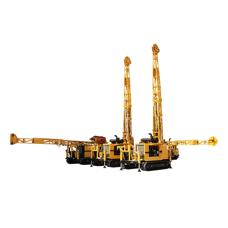
A modern coring drilling machine integrates surface power generation, structural support, and highly engineered downhole tools.
The surface infrastructure dictates the maximum capabilities of the entire operation. The power unit drives the hydraulic pumps that power all rig functions. Heavy-duty diesel engines dominate surface sites. Underground applications rely on electro-hydraulic systems to eliminate diesel emissions. The mast provides the structural framework to support the immense weight of the drill string. Mast structural ratings determine the maximum pullback capacity. This is the upward force the rig can exert to pull the drill rods out of the hole.
The control panel is the driller's interface with the subsurface environment. Modern rigs utilize advanced hydraulic feedback systems and Measurement While Drilling (MWD) digital data logging. These systems provide real-time metrics on torque, fluid pressure, RPM, and penetration rate. Drillers use this data to feel the rock formation through the machine. They make micro-adjustments to prevent core blockages or bit damage.
The drill string consists of hollow steel rods threaded together. They form a continuous conduit from the surface to the bit. These rods possess immense tensile strength to withstand rotational torque and downward pressure without snapping. The top drive is the mechanical heart of the rotational system. Older rotary table designs require manual chucking and unchucking of the rods. A hydraulic top drive moves vertically along the mast. This allows for continuous, smooth coring operations, faster rod handling, and superior control over torque and feed pressure.
The core barrel assembly is the primary downhole component for sample preservation. It utilizes a dual-tube architecture. The outer barrel connects directly to the drill string and rotates with the drill bit. The inner barrel suspends on bearings within the outer barrel and remains stationary. As the bit cuts downward, the core slides into the stationary inner barrel.
At the base of the inner barrel sits the core lifter and core lifter case. The core lifter is a slotted, tapered steel ring. When the driller stops the rotation and pulls the drill string upward, the core lifter case slides down over the tapered core lifter. This compresses it tightly against the rock sample. The action grips the core and snaps it off from the bedrock below. The sample is now secure inside the inner tube for retrieval.
Downhole Component Breakdown
Component | Primary Function | Operational Impact |
|---|---|---|
Outer Tube | Transmits rotation and weight to the bit | Maintains borehole gauge and protects inner tube |
Inner Tube | Receives and stores the core sample | Remains stationary to prevent sample degradation |
Core Lifter | Grips the base of the core sample | Snaps the core from bedrock during pullback |
Reaming Shell | Maintains exact hole diameter behind the bit | Prevents the hole from shrinking in abrasive rock |
The method used to retrieve the filled core barrel from the bottom of the hole dictates operational efficiency and site safety.
Retrieving the sample in a conventional system requires tripping the entire drill string out of the hole. If the bit is at a depth of 100 meters, the crew must pull up and unscrew 100 meters of drill rods just to access the core barrel. Once they empty the sample, they lower the entire 100-meter string back down to resume drilling. This method is highly inefficient at depth. Conventional coring is limited to shallow geotechnical surveys, environmental investigations, or short-run infrastructure testing. Target depths rarely exceed 30 to 50 meters.
Wireline systems changed deep geological exploration. Instead of removing the entire drill string, the inner core barrel is fully removable. When the inner tube is full, the driller lowers an overshot tool down the hollow center of the drill string using a high-tensile wireline cable. The overshot latches onto the top of the inner tube assembly. A surface winch pulls the inner tube and the core sample up to the surface. The outer drill rods and the bit remain at the bottom of the hole.
Wireline systems utilize standard sizing classifications. The choice of size impacts the sample volume, core recovery quality, and the maximum depth capacity of the rig. Larger diameters provide excellent sample mass for metallurgical testing but require more torque and reduce the rig's maximum depth. Smaller diameters allow rigs to reach extreme depths efficiently. Wireline is the standard for deep mineral exploration due to the massive time savings during core retrieval.
Standard Wireline Sizing Specifications
Size Designation | Hole Diameter (mm) | Core Diameter (mm) | Typical Application |
|---|---|---|---|
PQ | 122.6 | 85.0 | Bulk sampling, shallow coal exploration |
HQ | 96.0 | 63.5 | Standard mineral exploration, geotechnical |
NQ | 75.7 | 47.6 | Deep mineral exploration, hard rock |
BQ | 60.0 | 36.5 | Ultra-deep exploration, specialized underground |
Subsurface lithology varies from unconsolidated beach sands to solid granite. A versatile geological survey core drilling rig adapts its downhole tooling and drilling techniques to handle these extremes.
Standard rotational drilling obliterates unconsolidated materials like soft clays, loose sands, or highly weathered rock. The drilling fluid washes away the soft material before it enters the barrel. Drillers utilize punch core systems or specialized nested barrels to combat this. The inner barrel advances slightly ahead of the rotating outer bit. The inner barrel punches into the soft sediment, capturing the material before the flushing fluid washes it away. Spring-loaded inner barrels automatically retract when they hit harder rock. This allows the diamond bit to take over the cutting action without requiring a trip to the surface to change tools.
Crystalline or highly abrasive hard rock requires impregnated diamond bits. Synthetic industrial diamonds mix with a metallic powder and bake into a solid matrix on the cutting face of the bit. You must match the hardness of the metallic matrix to the hardness of the rock based on the Mohs hardness scale.
As the bit grinds against the hard rock, the metallic matrix wears away at a controlled rate. If the matrix is too hard for the rock, it will not wear away. The diamonds become blunt, and the bit stops cutting. Drillers call this polishing. If the matrix is too soft, it wears away too quickly. It releases the diamonds prematurely and destroys the bit in hours. Proper matrix selection ensures the bit wears just enough to constantly expose sharp, new cutting diamonds. This optimizes penetration rates and reduces consumable costs.
Procuring the correct equipment requires a systematic evaluation of project parameters against machine capabilities. Failing to align the rig's specifications with the site conditions guarantees operational failure.
Evaluation begins by defining the absolute baseline requirements of the project. You need to know the maximum target depth and the required core diameter. A climate analysis project requires large-diameter ice cores. A gold assay might only require standard NQ rock cores. Understanding the anticipated geological formations dictates the required torque and rotational speeds. Soft, sticky clays require high torque and low RPM. Hard, competent granite requires high RPM and lower torque.
The physical location of the drill site heavily influences rig selection. Surface operations require evaluating the footprint, power-to-weight ratio, and access capabilities of the chassis.
Skid-mounted rigs work best for flat, accessible terrain where bulldozers can drag them into position.
Crawler or track-mounted rigs offer excellent all-terrain mobility for rugged, muddy environments.
Truck-mounted rigs provide rapid mobilization between distant sites on established roads.
Heli-portable rigs break down into modular components for remote, mountainous, or jungle environments with zero road access. Crews fly the engine, mast, and pumps in separately and assemble them on a custom drill pad.
Underground applications demand entirely different architecture. Subterranean mineral exploration requires compact, electric-hydraulic rigs designed to operate in tight drifts and tunnels. These rigs feature specialized, articulating mast configurations capable of drilling at any angle, from vertically upward into the roof to vertically downward into the floor.
Operational budgets depend heavily on the management of consumables. A high-performance field exploration core drilling rig requires high-quality diamond bits, durable inner tubes, and robust wireline cables. Utilizing substandard rods or cheap bits leads to frequent tool failures, lost holes, and massive downtime. You must track the wear rates of downhole tools daily. Drillers log the footage achieved by each bit and the condition of the wireline cable after every shift.
Modern drilling operations adhere to strict mining and environmental regulations. Evaluating a rig's safety integrations is mandatory. Look for automated rod handlers that remove the need for crews to manually lift heavy steel rods. This reduces back injuries and crushed fingers. Interlocked safety cages around the rotating drill string prevent entanglement accidents. Hands-free hydraulic breakout systems eliminate the dangerous practice of using manual pipe wrenches under high tension. Rigs equipped with these features protect the crew and ensure compliance with site safety mandates.
Subsurface drilling presents constant mechanical and geological challenges. Experienced drillers anticipate risks and deploy specific mitigation strategies to maintain core recovery and protect the equipment.
Encountering highly fractured, vuggy, or swelling ground is a primary risk. Broken rock fragments wedge inside the inner tube, causing a core blockage. If drilling continues, the blocked core grinds against the incoming rock, resulting in total sample loss. Drillers utilize triple-tube core barrels to mitigate this. These barrels feature a split inner tube that encases the core, allowing for pristine extraction of fractured rock. Specialized drilling mud polymers encapsulate swelling clays and lubricate the barrel. The driller relies on precise hydraulic feedback to instantly detect a blockage. They adjust RPM and feed pressure in real-time, or stop to pull the tube before grinding occurs.
Selecting a rig with insufficient pullback capacity or torque for the target depth is a catastrophic error. As the hole gets deeper, the weight of the drill string increases. Friction against the borehole wall multiplies. If the rig lacks the power to overcome this friction, the pipe becomes stuck. This often happens due to differential sticking, where the hydrostatic pressure of the mud column pins the drill rods against a permeable rock formation. Attempting to pull a stuck pipe with an underpowered mast leads to structural failure or snapped cables. Mitigation requires a rigorous review of manufacturer depth capacity charts prior to procurement. You must derate these charts for the specific rod sizes being used, the viscosity of the drilling fluid, the condition of the borehole, and the elevation of the site. High altitudes reduce diesel engine power output.
Take the following actions to finalize your equipment selection and site preparation:
Consult with the lead geologist to define the exact sample diameters required for laboratory testing before ordering drill rods.
Request derated load and torque capacity charts from rig manufacturers to verify the machine can handle the target depth under worst-case friction scenarios.
Audit the proposed rig for automated rod handling and interlocked guarding to ensure full compliance with regional mining safety standards.
Establish a daily consumables tracking log to monitor diamond bit wear rates and wireline cable integrity throughout the drilling program.
A: A construction coring machine is a small, handheld tool used to cut shallow holes in concrete walls or floors for plumbing and electrical routing. A geological core drilling rig is a massive, heavy-duty machine designed to penetrate hundreds or thousands of meters into the earth to extract continuous rock or soil samples for scientific and industrial analysis.
A: Depth capacity depends on the rig's pullback power and the size of the drill rods. A mid-sized exploration rig using NQ-sized wireline rods typically drills between 1,000 and 1,500 meters. Large, deep-hole specialized rigs exceed 3,000 meters under optimal geological conditions.
A: The inner core barrel captures and protects the rock sample. It mounts on bearings so it remains stationary while the outer barrel and drill bit rotate around it. This isolation prevents the fragile core sample from being destroyed by rotational friction and vibration during the drilling process.
A: The core lifter is a slotted, tapered steel ring located at the bottom of the inner barrel. When the driller pulls the drill string upward, the tapered lifter case wedges against the core lifter, compressing it tightly around the rock. This grips the core and snaps it off from the bedrock.
A: The size is determined by the standardized diameter of the wireline drill rods and core barrels used. PQ yields a large core ideal for bulk testing but limits depth. NQ yields a smaller core but allows the rig to reach much greater depths due to reduced weight and friction.
A: Drillers prevent core loss by using triple-tube core barrels. These contain a split inner liner that holds fractured rock together during extraction. They also adjust drilling fluid mixtures with specialized polymers to stabilize the broken rock and carefully monitor hydraulic feedback to prevent grinding blockages.


